Introduction to Electrical and Electronic Symbols
Electrical and electronic symbols are the universal language of the engineering and technology world. They serve as essential tools for professionals, engineers, technicians, and hobbyists to communicate, design, and understand electrical and electronic systems. In this blog post, we will explore the most common electrical and electronic symbols, their meanings, and their applications.
Electrical Symbols
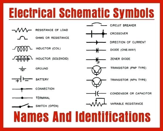
- Resistor: Represents a passive two-terminal electrical component used to limit the flow of electric current.
- Capacitor: A device used to store and release electrical energy.
- Inductor: Symbolizes a coil of wire that generates a magnetic field when current flows through it.
- Switches:
- SPST (Single-Pole, Single-Throw) Switch: A simple on/off switch.
- SPDT (Single-Pole, Double-Throw) Switch: A switch with one input and two possible outputs.
- DPDT (Double-Pole, Double-Throw) Switch: A switch with two inputs and two possible outputs.
- Connectors:
- Terminal Block: Used to connect wires together.
- Fuse: Represents a protective device that interrupts electrical flow in the event of overcurrent.
- Ground Symbol: Denotes a connection to ground, typically for safety.
- Power Sources:
- Battery: Represents a voltage source.
- AC Voltage Source: Represents an alternating current power source.
- DC Voltage Source: Represents a direct current power source.
Electronic Symbols
- Diodes:
- Light Emitting Diode (LED): Indicates a diode that emits light when current flows through it.
- Zener Diode: Represents a diode that maintains a constant voltage across its terminals.
- Schottky Diode: Symbolizes a diode with low voltage drop.
- Transistors:
- NPN Transistor: Denotes a bipolar junction transistor with an N-type material between two P-type materials.
- PNP Transistor: Represents a bipolar junction transistor with a P-type material between two N-type materials.
- Field Effect Transistor (FET): Symbolizes a transistor that controls current flow using an electric field.
- Integrated Circuits:
- Operational Amplifier (Op-Amp): Represents an electronic amplifier with two input terminals and one output terminal.
- Microcontroller: Symbolizes a compact computer on a single chip, used for controlling electronic systems.
- Digital Logic Gates: Include symbols for AND, OR, NOT, XOR, and other logic gates.
- Sensors:
- Temperature Sensor: Represents a device used to measure temperature.
- Photoresistor: Symbolizes a light-dependent resistor.
- Proximity Sensor: Denotes a sensor that detects the presence or absence of an object.
Applications
Understanding these symbols is crucial for a wide range of applications:
- Circuit Design: Engineers and designers use symbols to create and represent electrical and electronic circuits.
- Troubleshooting: Technicians rely on these symbols to diagnose and repair electrical and electronic systems.
- Education: Students and enthusiasts learn about electrical and electronic systems by studying these symbols.
- Manufacturing: Electronics manufacturers use these symbols in the production of devices and components.
Electrical Symbols & Electronic Symbols
Electrical symbols and electronic circuit symbols are used for drawing schematic diagram.
The symbols represent electrical and electronic components.
Table of Electrical Symbols
| Symbol | Component name | Meaning |
|---|---|---|
| Wire Symbols | ||
| Electrical Wire | Conductor of electrical current | |
| Connected Wires | Connected crossing | |
| Not Connected Wires | Wires are not connected | |
| Switch Symbols and Relay Symbols | ||
| SPST Toggle Switch | Disconnects current when open | |
| SPDT Toggle Switch | Selects between two connections | |
| Pushbutton Switch (N.O) | Momentary switch – normally open | |
| Pushbutton Switch (N.C) | Momentary switch – normally closed | |
| DIP Switch | DIP switch is used for onboard configuration | |
| SPST Relay | Relay open / close connection by an electromagnet | |
| SPDT Relay | ||
| Jumper | Close connection by jumper insertion on pins. | |
| Solder Bridge | Solder to close connection | |
| Ground Symbols | ||
| Earth Ground | Used for zero potential reference and electrical shock protection. | |
| Chassis Ground | Connected to the chassis of the circuit | |
| Digital / Common Ground | ||
| Resistor Symbols | ||
| Resistor (IEEE) | Resistor reduces the current flow. | |
| Resistor (IEC) | ||
| Potentiometer (IEEE) | Adjustable resistor – has 3 terminals. | |
| Potentiometer (IEC) | ||
| Variable Resistor / Rheostat (IEEE) | Adjustable resistor – has 2 terminals. | |
| Variable Resistor / Rheostat (IEC) | ||
| Trimmer Resistor | Preset resistor | |
| Thermistor | Thermal resistor – change resistance when temperature changes | |
| Photoresistor / Light dependent resistor (LDR) | Photo-resistor – change resistance with light intensity change | |
| Capacitor Symbols | ||
| Capacitor | Capacitor is used to store electric charge. It acts as short circuit with AC and open circuit with DC. | |
| Capacitor | ||
| Polarized Capacitor | Electrolytic capacitor | |
| Polarized Capacitor | Electrolytic capacitor | |
| Variable Capacitor | Adjustable capacitance | |
| Inductor / Coil Symbols | ||
| Inductor | Coil / solenoid that generates magnetic field | |
| Iron Core Inductor | Includes iron | |
| Variable Inductor | ||
| Power Supply Symbols | ||
| Voltage Source | Generates constant voltage | |
| Current Source | Generates constant current. | |
| AC Voltage Source | AC voltage source | |
| Generator | Electrical voltage is generated by mechanical rotation of the generator | |
| Battery Cell | Generates constant voltage | |
| Battery | Generates constant voltage | |
| Controlled Voltage Source | Generates voltage as a function of voltage or current of other circuit element. | |
| Controlled Current Source | Generates current as a function of voltage or current of other circuit element. | |
| Meter Symbols | ||
| Voltmeter | Measures voltage. Has very high resistance. Connected in parallel. | |
| Ammeter | Measures electric current. Has near zero resistance. Connected serially. | |
| Ohmmeter | Measures resistance | |
| Wattmeter | Measures electric power | |
| Lamp / Light Bulb Symbols | ||
| Lamp / light bulb | Generates light when current flows through | |
| Lamp / light bulb | ||
| Lamp / light bulb | ||
| Diode / LED Symbols | ||
| Diode | Diode allows current flow in one direction only – left (anode) to right (cathode). | |
| Zener Diode | Allows current flow in one direction, but also can flow in the reverse direction when above breakdown voltage | |
| Schottky Diode | Schottky diode is a diode with low voltage drop | |
| Varactor / Varicap Diode | Variable capacitance diode | |
| Tunnel Diode | ||
| Light Emitting Diode (LED) | LED emits light when current flows through | |
| Photodiode | Photodiode allows current flow when exposed to light | |
| Transistor Symbols | ||
| NPN Bipolar Transistor | Allows current flow when high potential at base (middle) | |
| PNP Bipolar Transistor | Allows current flow when low potential at base (middle) | |
| Darlington Transistor | Made from 2 bipolar transistors. Has total gain of the product of each gain. | |
| JFET-N Transistor | N-channel field effect transistor | |
| JFET-P Transistor | P-channel field effect transistor | |
| NMOS Transistor | N-channel MOSFET transistor | |
| PMOS Transistor | P-channel MOSFET transistor | |
| Misc. Symbols | ||
| Motor | Electric motor | |
| Transformer | Change AC voltage from high to low or low to high. | |
| Electric bell | Rings when activated | |
| Buzzer | Produce buzzing sound | |
| Fuse | The fuse disconnects when current above threshold. Used to protect circuit from high currents. | |
| Fuse | ||
| Bus | Contains several wires. Usually for data / address. | |
| Bus | ||
| Bus | ||
| Optocoupler / Opto-isolator | Optocoupler isolates connection to other board | |
| Loudspeaker | Converts electrical signal to sound waves | |
| Microphone | Converts sound waves to electrical signal | |
| Operational Amplifier | Amplify input signal | |
| Schmitt Trigger | Operates with hysteresis to reduce noise. | |
| Analog-to-digital converter (ADC) | Converts analog signal to digital numbers | |
| Digital-to-Analog converter (DAC) | Converts digital numbers to analog signal | |
| Crystal Oscillator | Used to generate precise frequency clock signal | |
| ⎓ | Direct current | Direct current is generated from constant voltage level |
| Antenna Symbols | ||
| Antenna / aerial | Transmits & receives radio waves | |
| Antenna / aerial | ||
| Dipole Antenna | Two wires simple antenna | |
| Logic Gates Symbols | ||
| NOT Gate (Inverter) | Outputs 1 when input is 0 | |
| AND Gate | Outputs 1 when both inputs are 1. | |
| NAND Gate | Outputs 0 when both inputs are 1. (NOT + AND) | |
| OR Gate | Outputs 1 when any input is 1. | |
| NOR Gate | Outputs 0 when any input is 1. (NOT + OR) | |
| XOR Gate | Outputs 1 when inputs are different. (Exclusive OR) | |
| D Flip-Flop | Stores one bit of data | |
| Multiplexer / Mux 2 to 1 | Connects the output to selected input line. | |
| Multiplexer / Mux 4 to 1 | ||
| Demultiplexer / Demux 1 to 4 | Connects selected output to the input line. | |
Conclusion
Electrical and electronic symbols are the building blocks of modern technology. They enable us to communicate complex circuit designs, troubleshoot issues, and understand the inner workings of electronic systems. Whether you’re an electrical engineer, a hobbyist, or just someone interested in technology, having a good grasp of these symbols is essential for success in the field of electronics.