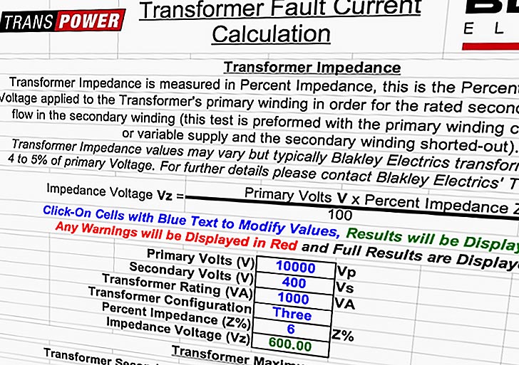
Current transformer (CT) saturation calculator
Current Transformer Performance Calculation
Current Transformer (CT) performance can be estimated using one of the following methods:
- Formula method
- Excitation curve method
- ANSI standards
Formula method
| Software: | Current transformer (CT) saturation calculator |
| Version: | – |
| Developer: | IEEE PSRC (Glenn Swift) |
| Size: | 2.30 MB (.xls) |
| Price: | Free |
| Theory: | Right here |
| Download: | Right here |
The formula method uses the fundamental transformer equation to calculate the effective flux density for a particular value of fault current. The calculated flux density is then compared to the capability of the steel used in the core of the CT and a determination is made whether the core will saturate or not for that fault current.
Obtaining the cross-sectional area and maximum flux density of the CT core is not easy and this method is only applicable in certain rare situations. This method is not discussed further.
Excitation method
Excitation curve represents a curve of CT secondary rms voltage plotted against rms current with the primary open circuited. The reasonably accurate secondary excitation curve for a given CT can be obtained by open circuiting the primary and applying AC voltage of appropriate frequency to the secondary. The current that flows in to the CT needs to be measured. The curve of applied rms terminal voltage vs rms secondary current is approximately the secondary excitation curve.
Introduction to the calculator
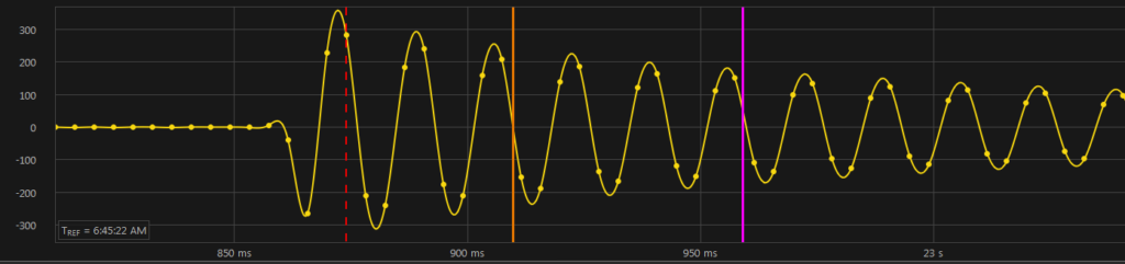
The spreadsheet ‘CT Saturation Calculator’ is intended to provide quick indication not only of whether or not a CT will saturate in a particular application, but also an accurate indication of the actual waves-hape of the secondary current so that the degree of saturation as a function of time is apparent. Furthermore, the data is available to the user to use as input to a digital relay model, if such is available.
The user can convert the data into a COMTRADE file, for example. There are many technical papers on the subject of modeling the behavior of iron-cored current transformers used for protective relaying purposes. One of the difficulties in using an elaborate model (in any field of engineering) is in getting the parameters in a particular case in order to implement that model easily, efficiently and accurately.
For example, the excitation current in the region below the knee-point is a complex combination of magnetizing, hysteresis and eddy-current components, the parameters of which are usually not known in a particular case.It turns out (can be shown) that, if the excitation current waveform reaches into the saturated region, the part of the waveform in the below-knee-point region has negligible effect on the overall solution. This simplifies the solution greatly, with little effect on accuracy.
If errors under low current, low burden conditions are of interest, a more elaborate model must be used.
Testing of the Model
The proof of the pudding is in the eating. Because this model is new and quite different from those in the literature, testing against real high-current laboratory results was important. To this end, two laboratory examples published in reference (*) were compared against results from this program. The agreement was very close.
In addition, the program has had widespread circulation, and to date there are two utility-user reports of agreement with previous results and no reports of disagreement.
(*) Tziouvaras, D.A., et al, Mathematical Models for Current, Voltage, and Coupling Capacitor Voltage Transformers
Instructions
The first step is to determine the saturation voltage (Vs) for the CT in question. This is defined as the rms excitation voltage corresponding to ten-per-cent error current. For example, for a nominal five-amp CT which is expected to handle 100 amps with a ten per cent error, the error current at the saturation voltage Vs, is ten amps.For maximum accuracy, this should be a measured value supplied by the manufacturer. For example, a C400 CT has a nominal Vs of 400 volts rms, but the actual measured Vs will be a higher value; it could be 420 volts rms for example.
Incidentally, the actual measurements by the manufacturer may not have been made with a “true rms” meter. It has been determined that the error due to use of a “rectified average” type meter, for example, is not significant.
Second step is to determine the slope (1/S) of the upper part of the saturation curve, being careful that the curve is plotted on log-log scales with the decade spacing equal on both axes. “S” is defined as the reciprocal of this slope. You should get a slope such that S is in the neighborhood of 15 < S < 25. Note that the result is not very sensitive to the value of S.
Third and the last step: Enter other parameters such as the CT winding resistance, the burden, the degree of dc-offset in the primary current waveform (up to 1 per unit), the primary system X/R ratio, the remanence (*), and the primary symmetrical rms current.
Once any change to an INPUT parameter is made, a new plot appears automatically. The scale adjustment is automatic and the plot is believed to be self-explanatory.This is a definition used in the Guide that is not strictly correct but is used here to be consistent with the Guide. If the ideal (maximum rated) secondary current is 100 amps rms and the exciting (error) current is 10 amps rms, then the actual secondary current is typically 99+ amps rms, not 90 amps rms. This is because the exciting current is both out of phase and non-sinusoidal, so simple subtraction does not apply.
So when we specify 10 amps error current at 100 amps secondary current, the error is actually less than 1% typically, but includes a phase error of, say 5 degrees, leading.