Excel Spreadsheets for Grounding System Design Calculations of AC Substation
Today, I will introduce to you, the most powerful excel spreadsheet for Grounding System Design Calculations of AC Substation.
Important Use this excel spreadsheet for AC Substation only, and don’t use it for Domestic, commercial and industrial premises. (Please review the above definition for domestic, commercial and industrial premises). |
Benefits For Using This Excel Spreadsheet
- List all data that must be known in the starting of Grounding System Design Calculations for AC Substation ,
- Facilitate the design process by using the auto excel mathematical functions in performing the calculations,
- Provide a professional design concept for any Grounding System of AC Substation as per Standard IEEE 80-2000,
- Provide and make reference for all used equations from IEEE 80-2000 Standard,
- Provide a printable Results Summary Report.
This excels spreadsheet includes (5) nos. worksheets and (9) nos. pages (see below image) as follows:
| S/N | Worksheet Name | No. of Pages |
| 1 | Table Of Contents | 1 |
| 2 | Design Procedure Block Diagram | 1 |
| 3 | Grounding System Calculations | 5 |
| 4 | Results Summary Report | 1 |
| 5 | Used Tables | 1 |
| Total | 9 |

First: Table of Contents Worksheet
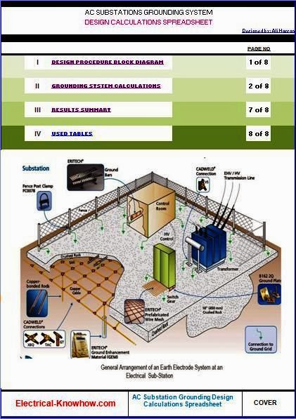
This worksheet lists the other worksheets in an index as shown in below figure, you can go to a specific worksheet by just clicking on its name.
You can send email to me directly by clicking on the phrase “Designed by: Ali Hassan” for any inquiries or notes.

Second: Design Procedure Block Diagram Worksheet
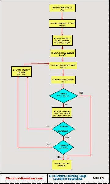
This worksheet includes the block diagram which illustrates the sequences of steps to design the ground grid of AC Substations and it is divided to (2) types of shapes as follows:
- Rectangular shapes: for data entering and data calculation,
- Diamond shape: for logical comparison between different values.
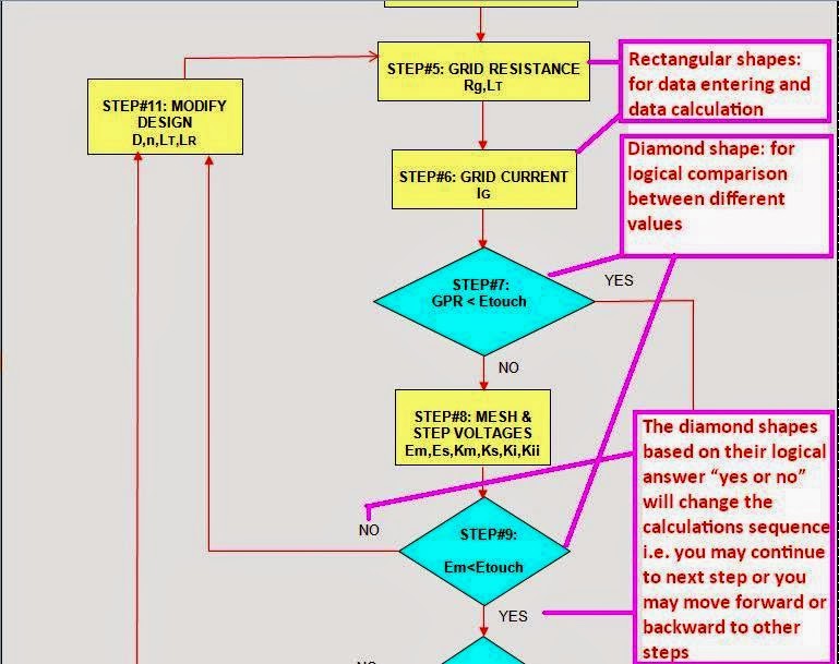
Note: The diamond shapes based on their logical answer “yes or no” will change the calculations sequence i.e. you may continue to next step or you may move forward or backward to other steps.
Third: Grounding System Calculations Worksheet

This worksheet includes general data that must be known in the starting of Grounding System Design Calculations of AC Substations, which are included in step#1 as follows:
- Soil Resistivity, ρ
- Gravel Resistivity, ρs
- Symmetrical Short Circuit Current, Ig
- Duration of Earth Fault Current, ts
- Maximum Allowable Conductor Temperature
- Design Ambient Temperature
- Thickness of Crushed Gravel, hs
- Depth of Earth Grid, h
- Reference depth of the Grid, ho

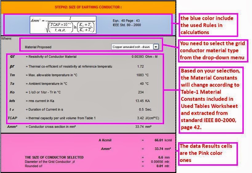
Important: The data input cells are the yellow color ones |
ImportantThe blue areas include the used rules in calculations referred to Standard IEEE 80-2000,The gray areas list the design parameters description included in each Rule.The light green areas include the intermediate data results that will be used in getting the required data results in pink areas. |
Also, this worksheet helps you to calculate the following:
- Step#2: The size of the grid conductor in Kcmil, mm2 and its diameter
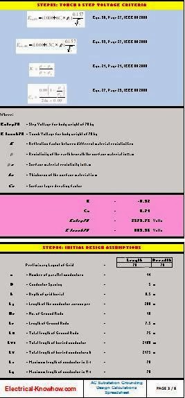
- Step#3: Tolerable touch voltage and step voltages (Etouch and Estep)
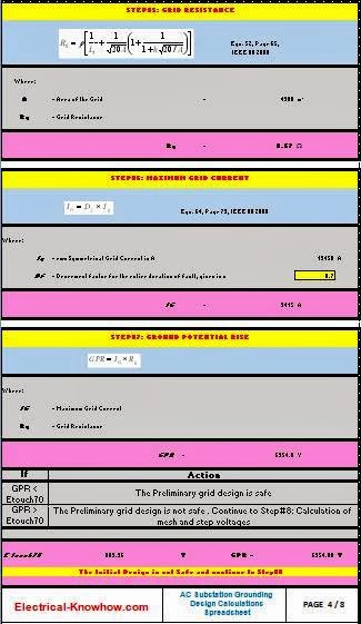
- Step#5: Grid resistance calculation, Rg
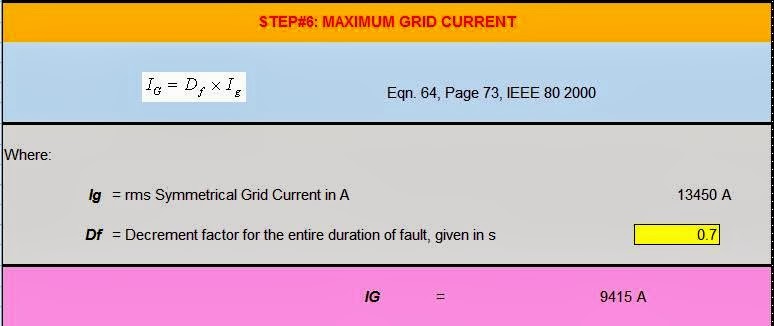
- Step#6: Maximum Grid Current calculation, IG
- Step#7: Ground Potential Rise GPR
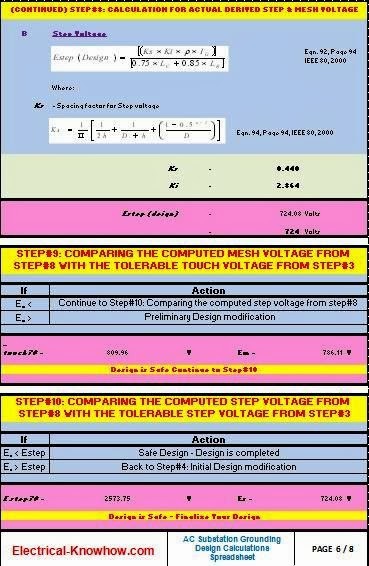
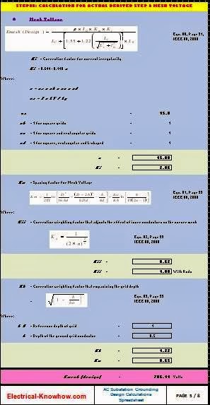
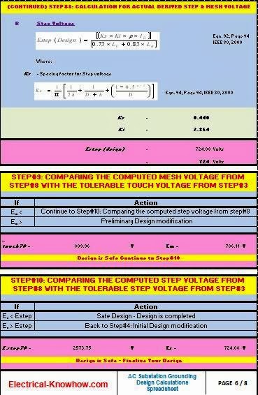
- Step#8: Calculation for Actual Derived Step & Mesh Voltage (Es and Em)
For step#2 You need to select the grid conductor material type from the drop-down menu existing in this step, the choices are: Copper, annealed soft-drawnCopper, commercial hard-drawnCopper-clad steel wireCopper-clad steel wireCopper-clad steel rodAluminum, EC gradeAluminum, 5005 alloyAluminum, 6201 alloyAluminum-clad steel wireSteel, 1020Stainless-clad steel rodZinc-coated steel rodStainless steel, 304 |
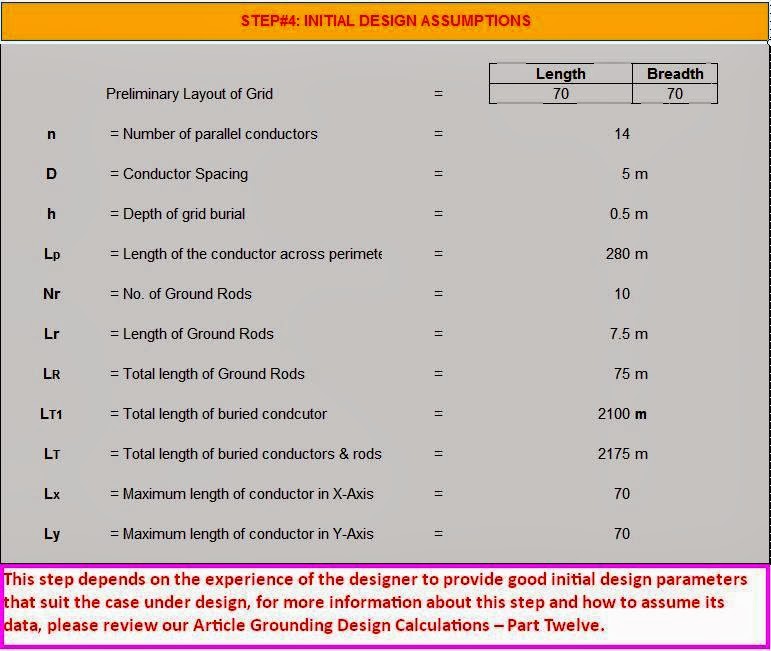
For Step#4: Initial Design Assumptions
This step depends on the experience of the designer to provide good initial design parameters that suit the case under design, for more information about this step and how to assume its data,

In addition to the above, this worksheet helps you to logically compare between the different designs parameters as follows:
- In Step#7: comparing the computed GPR with the Tolerable Touch Voltage from Step#3,
- In Step#9: Comparing the Computed Mesh Voltage from Step#8 with the Tolerable Touch Voltage from Step#3,
- In Step#10: Comparing the Computed Step Voltage from Step#8 with the Tolerable Step Voltage from Step#3.
This worksheet gives results summary under three sections as follows:
Section#1: Earth Grid Conductor, it gives:
- Type of Conductor,
- Size of Conductor,
- Length of Conductor,
- Depth of Conductor.
Section#2: Ground Rods, it gives:
- Total Length of Ground Rods,
- Length of Individual Ground Rods,
- No. of Ground Rods.
Section#3: Human Safety, it gives:
- The permissible (Tolerable) values of the touch and step voltages,
- The designed value of the touch and step voltages,
- The result of logical comparison between the Computed Mesh Voltage from Step#8 with the Tolerable Touch Voltage from Step#3,
- The result of logical comparison between the Computed Step Voltage from Step#8 with the Tolerable Step Voltage from Step#3.
Fifth: Used Tables Worksheet


Dear Sir
How do I get a special earthing calculation excel
Thank’s